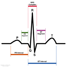
A typical ECG tracing of the cardiac cycle (heartbeat) consists of a P wave, a QRS complex, a T wave, and a U wave which is normally visible in 50 to 75% of ECGs. The baseline voltage of the electrocardiogram is known as the isoelectric line. Typically the isoelectric line is measured as the portion of the tracing following the T wave and preceding the next P wave.
| Feature | Description | Duration |
|---|---|---|
| RR interval | The interval between an R wave and the next R wave is the inverse of the heart rate. Normal resting heart rate is between 50 and 100 bpm | 0.6 to 1.2s |
| P wave | During normal atrial depolarization, the main electrical vector is directed from the SA node towards the AV node, and spreads from the right atrium to the left atrium. This turns into the P wave on the ECG. | 80ms |
| PR interval | The PR interval is measured from the beginning of the P wave to the beginning of the QRS complex. The PR interval reflects the time the electrical impulse takes to travel from the sinus node through the AV node and entering the ventricles. The PR interval is therefore a good estimate of AV node function. | 120 to 200ms |
| PR segment | The PR segment connects the P wave and the QRS complex. This coincides with the electrical conduction from the AV node to the bundle of His to the bundle branches and then to the Purkinje Fibers. This electrical activity does not produce a contraction directly and is merely traveling down towards the ventricles and this shows up flat on the ECG. The PR interval is more clinically relevant. | 50 to 120ms |
| QRS complex | The QRS complex reflects the rapid depolarization of the right and left ventricles. They have a large muscle mass compared to the atria and so the QRS complex usually has a much larger amplitude than the P-wave. | 80 to 120ms |
| J-point | The point at which the QRS complex finishes and the ST segment begins. Used to measure the degree of ST elevation or depression present. | N/A |
| ST segment | The ST segment connects the QRS complex and the T wave. The ST segment represents the period when the ventricles are depolarized. It is isoelectric. | 80 to 120ms |
| T wave | The T wave represents the repolarization (or recovery) of the ventricles. The interval from the beginning of the QRS complex to the apex of the T wave is referred to as the absolute refractory period. The last half of the T wave is referred to as the relative refractory period (or vulnerable period). | 160ms |
| ST interval | The ST interval is measured from the J point to the end of the T wave. | 320ms |
| QT interval | The QT interval is measured from the beginning of the QRS complex to the end of the T wave. A prolonged QT interval is a risk factor for ventricular tachyarrhythmias and sudden death. It varies with heart rate and for clinical relevance requires a correction for this, giving the QTc. | 300 to 430ms[citation needed] |
| U wave | The U wave is not always seen. It is typically low amplitude, and, by definition, follows the T wave. | |
| J wave | The J wave, elevated J-Point or Osborn Wave appears as a late delta wave following the QRS or as a small secondary R wave . It is considered pathognomic of hypothermia or hypocalcemia. |
There were originally four deflections, but after the mathematical correction for artifacts introduced by early amplifiers, five deflections were discovered. Einthoven chose the letters P, Q, R, S, and T to identify the tracing which was superimposed over the uncorrected labeled A, B, C, and D.
In intracardiac electrocardiograms, such as can be acquired from pacemaker sensors, an additional wave that can be seen is the H deflection, which reflects the depolarization of the bundle of His. The H-V interval, in turn, is the duration from the beginning of the H deflection to the earliest onset of ventricular depolarization recorded in any lead.
source : en.wikipedia
source : en.wikipedia


0 comments:
Post a Comment